Home
› 0-30V Variable Power Supply Circuit Diagram / LM317 VARIABLE POWER SUPPLY Circuit Diagram | Circuits Diagram Lab - In this circuit, the maximum voltage at the output should be 30v so a 30v.
0-30V Variable Power Supply Circuit Diagram / LM317 VARIABLE POWER SUPPLY Circuit Diagram | Circuits Diagram Lab - In this circuit, the maximum voltage at the output should be 30v so a 30v.
0-30V Variable Power Supply Circuit Diagram / LM317 VARIABLE POWER SUPPLY Circuit Diagram | Circuits Diagram Lab - In this circuit, the maximum voltage at the output should be 30v so a 30v.. Will it work at first power on? High efficiency variable regulator that new circuit design using ic regulator ua723 and best for who is finding circuits: Use a proper heat sink to fix both transistors. For testing electronic circuits or components and for bench power supply we need adjustable voltage regulator to provide voltage some sensitive electronic components and integrated circuits requires constant current source power supply hence we designed simple and easy to … The above universal power supply circuit provides a variable voltage between 3 to 30v, the maximum current of 1.5a and addition of modules can provide a higher current.
The mains features of this power supply is that it is highly flexible, and will allow you to get a variable voltage from 0 to 30 v, and a variable current from referring to the above proposed universal power supply circuit diagram, the functional details can be understood with the help of the flowing points Because it is high current, normal parts, a new circuit design. Will it work at first power on? High efficiency variable regulator that new circuit design using ic regulator ua723 and best for who is finding circuits: This is a high quality power supply with a continuously variable stabilised output adjustable at any value between 0 and 30vdc.
0 30V VARIABLE POWER SUPPLY CIRCUIT DIAGRAM PDF - Auto Electrical Wiring Diagram from i0.wp.com This variable power supply unit contains button interface for the voltage programming. High efficiency variable regulator that new circuit design using ic regulator ua723 and tip3055 easy to build and small as power protect over load maximum 3a. When the resistors r1 and r2 are added the equation for the output voltage of 7805 becomes vout= vfixed. The circuit of arduino controlled variable power supply is fabricated around constant voltage regulator ic and high current adjustable voltage regulator. This is a high quality power supply with a continuously variable stabilised output adjustable at any value between 0 and 30vdc. Circuit diagram of voltage regulator for adjustable 0 to 30v 2a dc power supply. In this circuit, the maximum voltage at the output should be 30v so a 30v. Because it is high current, normal parts, a new circuit design.
This is attained by adding two resistors r1 and r2 as shown in figure.
This circuit diagram is given below. The voltage across output is not completely. Because it has a few parts,small,and cheapest than others circuit that same power. This is attained by adding two resistors r1 and r2 as shown in figure. Use a proper heat sink to fix both transistors. For testing electronic circuits or components and for bench power supply we need adjustable voltage regulator to provide voltage some sensitive electronic components and integrated circuits requires constant current source power supply hence we designed simple and easy to … Will it work at first power on? Having a variable regulated power supply that can output precise voltages in the 0. This variable power supply unit contains button interface for the voltage programming. The circuit for variable voltage unit using arduino is shown in below diagram. Single power supply switch plus or minus power circuit diagram. +24v dc is directly obtained from positive terminal of capacitor c1 shown in circuit diagram. High efficiency variable regulator that new circuit design using ic regulator ua723 and best for who is finding circuits:
You can read the comments below for more details. Use a proper heat sink to fix both transistors. You will able to adjust the output voltage from 0 volt up to 30 volt dc. Having a variable regulated power supply that can output precise voltages in the 0. This is a high quality power supply with a continuously variable stabilised output adjustable at any value between 0 and 30vdc.
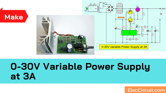
0-30V Variable Power Supply circuit Diagram at 3A - ElecCircuit.com from www.eleccircuit.com Because it has a few parts,small,and cheapest than others circuit that same power. The circuit of arduino controlled variable power supply is fabricated around constant voltage regulator ic and high current adjustable voltage regulator. Single power supply switch plus or minus power circuit diagram. As a common effort of several people, this circuit diagram comes with several improvements. For testing electronic circuits or components and for bench power supply we need adjustable voltage regulator to provide voltage some sensitive electronic components and integrated circuits requires constant current source power supply hence we designed simple and easy to … Will it work at first power on? This is the circuit diagram of voltage and current regulator circuit that can give 2 power transistor 2n3055 used in this circuit to control the output current. In the power supply circuit designed here, bipolar junction transistor 2n3055 works in the linear mode along with a variable resistance.
This is the circuit diagram of voltage and current regulator circuit that can give 2 power transistor 2n3055 used in this circuit to control the output current.
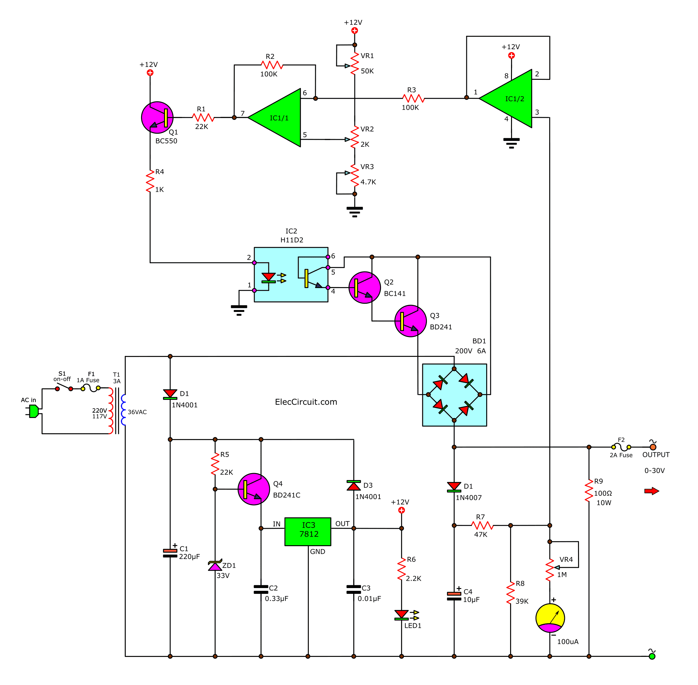
Similarly, one output of bridge rectifier is also. In this circuit, the maximum voltage at the output should be 30v so a 30v. From the circuit diagram i have r7 is the only component connected in the return loop. Circuit diagram of voltage regulator for adjustable 0 to 30v 2a dc power supply. This circuit diagram shows you how to make a 5v to 12v variable dc power supply from a fixed 5v regulator ic 7805. While it is no powerhouse, it is quite satisfactory for testing all preamps, many other projects, and even most power amps, as long as there is no speaker connected. You will able to adjust the output voltage from 0 volt up to 30 volt dc. The power mosfet q1 is controlled the current output, with using the resistor r3 500k adjust the voltage gate. Single power supply switch plus or minus power circuit diagram. Use a proper heat sink to fix both transistors. This variable power supply unit contains button interface for the voltage programming. In the power supply circuit designed here, bipolar junction transistor 2n3055 works in the linear mode along with a variable resistance. The circuit for variable voltage unit using arduino is shown in below diagram.
This circuit is best for you. The circuit for variable voltage unit using arduino is shown in below diagram. Will it work at first power on? In the power supply circuit designed here, bipolar junction transistor 2n3055 works in the linear mode along with a variable resistance. Similarly, one output of bridge rectifier is also.
AC variable power supply, 0-30V 3A from www.eleccircuit.com Because it has a few parts,small,and cheapest than others circuit that same power. The circuit of arduino controlled variable power supply is fabricated around constant voltage regulator ic and high current adjustable voltage regulator. Because it is high current, normal parts, a new circuit design. High efficiency variable regulator that new circuit design using ic regulator ua723 and tip3055 easy to build and small as power protect over load maximum 3a. From the circuit diagram i have r7 is the only component connected in the return loop. The above universal power supply circuit provides a variable voltage between 3 to 30v, the maximum current of 1.5a and addition of modules can provide a higher current. When the resistors r1 and r2 are added the equation for the output voltage of 7805 becomes vout= vfixed. High efficiency variable regulator that new circuit design using ic regulator ua723 and best for who is finding circuits:
0 to 12 volt variable power supply using bd139 transistor.
For testing electronic circuits or components and for bench power supply we need adjustable voltage regulator to provide voltage some sensitive electronic components and integrated circuits requires constant current source power supply hence we designed simple and easy to … This is the circuit diagram of voltage and current regulator circuit that can give 2 power transistor 2n3055 used in this circuit to control the output current. In the power supply circuit designed here, bipolar junction transistor 2n3055 works in the linear mode along with a variable resistance. As a common effort of several people, this circuit diagram comes with several improvements. This is a high quality power supply with a continuously variable stabilised output adjustable at any value between 0 and 30vdc. Circuit diagram of voltage regulator for adjustable 0 to 30v 2a dc power supply. You will able to adjust the output voltage from 0 volt up to 30 volt dc. Similarly, one output of bridge rectifier is also. Figure 1 shows the complete circuit diagram, and it. Having a variable regulated power supply that can output precise voltages in the 0. Single power supply switch plus or minus power circuit diagram. From the circuit diagram i have r7 is the only component connected in the return loop. The circuit for variable voltage unit using arduino is shown in below diagram.