Define Schematic Diagram : Electrical Drawings And Schematics Overview - Relating to or of the nature of a diagram or scheme.. Showing the main form and features of something, usually in the form of a drawing, in a way that…. Also known as schematic drawing; A drawing or plan that outlines and explains the parts, operation, etc., of something: A chart, plan, or scheme. These static aspects represent those parts of a diagram, which forms the main structure and are therefore stable.
Dividing a system into multiple class diagrams makes the system easier to understand, especially if each diagram is a graphical representation of a specific part of the system. A drawing or plan that outlines and explains the parts, operation, etc., of something: A graphical representation of a system. Define sequence diagrams a sequence diagram is a behavior diagram that represents the interaction between structural elements of an architecture as a sequence of message exchanges. Schemas help people organize their knowledge of the world and understand new information.
Circuit Diagram Simple Circuits Electricity And Circuits Don T Memorise Youtube from i.ytimg.com They illustrate such items as the size, type, component part number, and component location in relationship to the other circuit components. A diagram of an engine. What is schematic diagram definition of schematic diagram: A schematic diagram is a picture that represents the components of a process, device, or other object using abstract, often standardized symbols and lines. Adjective pertaining to or of the nature of a schema, diagram, or scheme; A schema diagram only shows us the database design. Schematic diagrams define the components of the article that constitute a complete set and the interconnections between components; They capture the interaction between objects in the context of a collaboration.
It does not show the actual data of the database.
Schematic diagram also found in: Showing the main form and features of something, usually in the form of a drawing, in a way that…. Relating to or of the nature of a diagram or scheme. A structural or procedural diagram, especially of an electrical or mechanical system. A schematic, or schematic diagram, is a representation of the elements of a system using abstract, graphic symbols rather than realistic pictures. These static aspects represent those parts of a diagram, which forms the main structure and are therefore stable. Define sequence diagrams a sequence diagram is a behavior diagram that represents the interaction between structural elements of an architecture as a sequence of message exchanges. The definition and use of constraint blocks is represented on a block definition diagram and parametric diagram, respectively. Electrical schematic diagram | elementary & wiring diagram electrical schematic diagrams convey specific information to the technician. Schematic diagrams only depict the significant components of a system, though some details in the diagram may also be exaggerated or introduced to facilitate the understanding of the system. They illustrate such items as the size, type, component part number, and component location in relationship to the other circuit components. A piping and instrumentation diagram (p&id) is a detailed diagram in the process industry which shows the piping and process equipment together with the instrumentation and control devices. The schematic diagram is a symbolic presentation of a system's control elements that makes it easier to understand an electrical system's functional logic.
A piping and instrumentation diagram (p&id) is a detailed diagram in the process industry which shows the piping and process equipment together with the instrumentation and control devices. Schematic diagrams only depict the significant components of a system, though some details in the diagram may also be exaggerated or introduced to facilitate the understanding of the system. A schema is an outline, diagram, or model. The four structural diagrams are − A structural or procedural diagram, especially of an electrical or mechanical system.
Schematics And Wiring Diagrams Circuit 1 from www.industrial-electronics.com Schematic diagrams define the components of the article that constitute a complete set and the interconnections between components; These static parts are represented by classes, interfaces, objects, components, and nodes. The definition and use of constraint blocks is represented on a block definition diagram and parametric diagram, respectively. A drawing or plan that outlines and explains the parts, operation, etc., of something: Superordinate to the p&id is the process flow diagram (pfd) which indicates the more general flow of plant processes and the relationship between major equipment of a plant facility. Updated july 22, 2019 a schema is a cognitive structure that serves as a framework for one's knowledge about people, places, objects, and events. You can use it as a flowchart maker, network diagram software, to create uml online, as an er diagram tool, to design database schema, to build bpmn online, as a circuit diagram maker, and more. English language learners definition of schematic technical :
Superordinate to the p&id is the process flow diagram (pfd) which indicates the more general flow of plant processes and the relationship between major equipment of a plant facility.
Sequence diagrams are time focus and they show the order of the interaction visually by using the vertical axis of the diagram to represent time what messages are sent and when. A structural or procedural diagram, especially of an electrical or mechanical system. 7.1.1 defining constraints using the block definition diagram block definition diagrams are used to define constraint blocks in a similar way to which they are used to define blocks. Dividing a system into multiple class diagrams makes the system easier to understand, especially if each diagram is a graphical representation of a specific part of the system. It does not show the actual data of the database. English language learners definition of schematic technical : Instead of modeling every entity and its relationships on a single class diagram, it is better to use multiple class diagrams. The schematic diagram is a symbolic presentation of a system's control elements that makes it easier to understand an electrical system's functional logic. Schematics typically show devices like the electrical power bus, breakers, fuses, electrical loads like relays and breakers, relay contacts, switches, and indicator lights. You can use sequence diagrams to describe how the parts of a static system interact. Electrical schematic diagram | elementary & wiring diagram electrical schematic diagrams convey specific information to the technician. They capture the interaction between objects in the context of a collaboration. How to use diagram in a sentence.
In computing, schemas are often used to describe the structure of different types of data. A schematic diagram is a picture that represents the components of a process, device, or other object using abstract, often standardized symbols and lines. The four structural diagrams are − Adjective pertaining to or of the nature of a schema, diagram, or scheme; A schema diagram only shows us the database design.
Wiring Diagram Edrawmax from images.edrawsoft.com A schema diagram is a diagram which contains entities and the attributes that will define that schema. English language learners definition of schematic technical : A graphical representation of a system. Noun a figure, usually consisting of a line drawing, made to accompany and illustrate a geometrical theorem, mathematical demonstration, etc. Define sequence diagrams a sequence diagram is a behavior diagram that represents the interaction between structural elements of an architecture as a sequence of message exchanges. The four structural diagrams are − Schematic diagrams only depict the significant components of a system, though some details in the diagram may also be exaggerated or introduced to facilitate the understanding of the system. They capture the interaction between objects in the context of a collaboration.
Uml sequence diagrams are interaction diagrams that detail how operations are carried out.
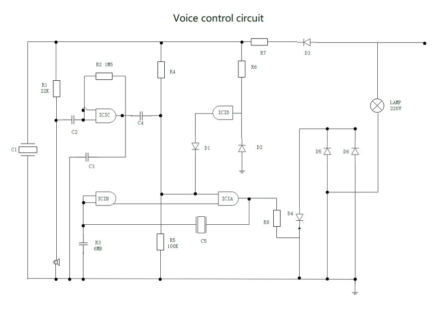
The structural diagrams represent the static aspect of the system. A schema is an outline, diagram, or model. A piping and instrumentation diagram (p&id) is a detailed diagram in the process industry which shows the piping and process equipment together with the instrumentation and control devices. Sequence diagrams are time focus and they show the order of the interaction visually by using the vertical axis of the diagram to represent time what messages are sent and when. Flowchart maker and online diagram software. These static aspects represent those parts of a diagram, which forms the main structure and are therefore stable. For example this is a schematic diagram of fm receiver: A structural or procedural diagram, especially of an electrical or mechanical system. A structural or procedural diagram, especially of an electrical or mechanical system. Instead of modeling every entity and its relationships on a single class diagram, it is better to use multiple class diagrams. The schematic diagram is a symbolic presentation of a system's control elements that makes it easier to understand an electrical system's functional logic. Electrical schematic diagram | elementary & wiring diagram electrical schematic diagrams convey specific information to the technician. Dividing a system into multiple class diagrams makes the system easier to understand, especially if each diagram is a graphical representation of a specific part of the system.