Home
› Types Of Electrical Circuits Diagrams - Schematic Diagram Software : Among these you'll find commonly used electrical drawings and schematics, like circuit diagrams, wiring diagrams, electrical plans and block diagrams.
Types Of Electrical Circuits Diagrams - Schematic Diagram Software : Among these you'll find commonly used electrical drawings and schematics, like circuit diagrams, wiring diagrams, electrical plans and block diagrams.
Types Of Electrical Circuits Diagrams - Schematic Diagram Software : Among these you'll find commonly used electrical drawings and schematics, like circuit diagrams, wiring diagrams, electrical plans and block diagrams.. Block diagrams are used extensively to show complex instrument channels and other complex systems when only the flowpath of the signal is important. The electronic plans represent the most detailed category of electronic drawings. Ladder diagram are electrical diagrams that represents an electrical circuits in industries to document control logic systems. Types of resistor and their symbols, and selection of resistors; Types of electrical circuits with diagram
The two most commonly used are the wiring diagram and the schematic diagram. These two different types of circuit diagrams are called pictorial (using basic images) or schematic style (using industry standard symbols). The circuit symbols are mostly used to draw the electronic circuits like switches, wires, sources, ground, resistor, capacitor, diodes, inductors, logic gates, transistors, amplifiers, transformer, antenna, etc. Electric circuit diagrams often have more or different parts shown using symbols. There are two vertical lines;
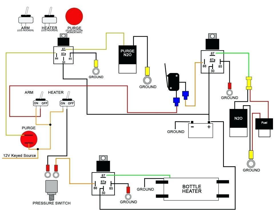
DIAGRAM General Motors Wiring Diagram FULL Version HD Quality Wiring Diagram - TUBEWIRING.EFRAN.IT from electricala2z.com Circuit diagrams or schematic diagrams show electrical connections of wires or conductors by using a node as shown in the image below. There are two vertical lines; Block diagrams are the simplest type of drawing. Diagram of a series circuit › circuits can be drawn as lines and symbols. They illustrate each component of the circuit, the technical information of the component (such as its ratings) and how each component is wired into the circuit. The pictorial style circuit diagram would be used for a broader, less technical audience. Types of resistor and their symbols, and selection of resistors; The use of block diagrams is not restricted to electronic circuits.
They illustrate each component of the circuit, the technical information of the component (such as its ratings) and how each component is wired into the circuit.
Electrical diagrams are drawings which are used to represent electrical circuits, these circuits are represented by using lines, symbols, and number combinations. See more ideas about diagram, electrical wiring diagram, house wiring. The use of block diagrams is not restricted to electronic circuits. They are wiring, schematic, and pictorial diagrams. Diagram of a series circuit › circuits can be drawn as lines and symbols. Diagrams, and block diagrams, and how each is used to describe circuit performance and function • recognize common electrical component symbols and drawing conventions that describe circuits • recognize and describe the configuration of common circuit building blocks such as power supplies, oscillators, amplifiers, load drivers, and digital. These two different types of circuit diagrams are called pictorial (using basic images) or schematic style (using industry standard symbols). Wires connect the other components of the circuit. In this lesson, learn how to use a circuit diagram to calculate the current in different. Electric circuit diagrams often have more or different parts shown using symbols. An electric circuit is the conductive path for the flow of current is called an electric circuit. To be able to read and understand an electric circuit diagram, you need to know the different parts and the. Electrical diagrams show the wiring between components and the relative position of the components.with the help of the electrical diagram we could get a better understanding of the electric circuits.
In electric circuits this charge is often carried by moving electrons in a wire.the si unit for measuring a. Electrical diagrams are drawings which are used to represent electrical circuits, these circuits are represented by using lines, symbols, and number combinations. The use of block diagrams is not restricted to electronic circuits. An on/ off switch also used between the source and load. A node is simply a filled circle or dot.
PPT - Electricity & Types of Circuits- Page 4 PowerPoint Presentation - ID:2321019 from image1.slideserve.com The block diagram is the most basic and easiest to understand of all the types of engineering prints. It resemble a ladder which is why it is named ladder diagram. Electric circuit diagrams show you how to connect the parts of a circuit, but they also can do a lot more! Electronic prints fall into two basic categories, electronic schematics and block diagrams. Among these you'll find commonly used electrical drawings and schematics, like circuit diagrams, wiring diagrams, electrical plans and block diagrams. Each component has its own symbol. The circuit symbols are mostly used to draw the electronic circuits like switches, wires, sources, ground, resistor, capacitor, diodes, inductors, logic gates, transistors, amplifiers, transformer, antenna, etc. You can depict a complex electrical circuit with the standard and simplified electrical symbols.
Under this situation, the value of current flow depends on load.
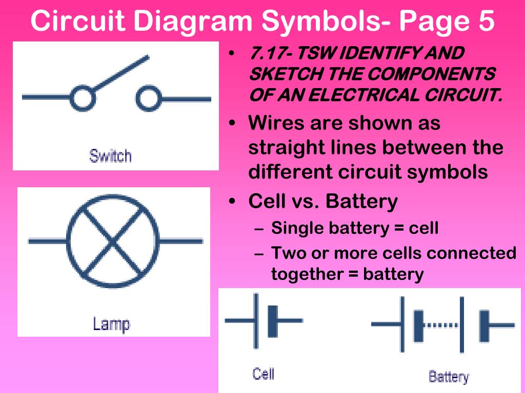
The circuit symbols are mostly used to draw the electronic circuits like switches, wires, sources, ground, resistor, capacitor, diodes, inductors, logic gates, transistors, amplifiers, transformer, antenna, etc. Electric circuit diagrams show you how to connect the parts of a circuit, but they also can do a lot more! Electric circuit diagrams often have more or different parts shown using symbols. They illustrate each component of the circuit, the technical information of the component (such as its ratings) and how each component is wired into the circuit. Each component has its own symbol. Block diagrams are the simplest type of drawing. A node is simply a filled circle or dot. There are some standard symbols to represent the components in a circuits. There are two vertical lines; The two light bulbs will produce light, because the circuit is unbroken. Diagram of a series circuit › circuits can be drawn as lines and symbols. They are wiring, schematic, and pictorial diagrams. Diagrams, and block diagrams, and how each is used to describe circuit performance and function • recognize common electrical component symbols and drawing conventions that describe circuits • recognize and describe the configuration of common circuit building blocks such as power supplies, oscillators, amplifiers, load drivers, and digital.
Lots of circuits similar to this interlocking circuit are used in industries. Right click on the diagram/key/fuse box you want to download; Some of the fuse boxes pictured in the diagrams are You can depict a complex electrical circuit with the standard and simplified electrical symbols. In electric circuits this charge is often carried by moving electrons in a wire.the si unit for measuring a.
Android için House Wiring Electrical Diagram - APK'yı İndir from image.winudf.com Under this situation, the value of current flow depends on load. Electronic prints fall into two basic categories, electronic schematics and block diagrams. Types, definition, specifications and application of capacitor; They are wiring, schematic, and pictorial diagrams. Electrical diagrams show the wiring between components and the relative position of the components.with the help of the electrical diagram we could get a better understanding of the electric circuits. The battery creates the current in the circuit. These electrical and electronics circuit symbols are used in circuit diagrams to explain how a circuit is interconnected. Circuit diagrams are widely used for circuit design, construction, and maintenance of electrical and electronic equipment.
Circuit diagrams are widely used for circuit design, construction, and maintenance of electrical and electronic equipment.
They are wiring, schematic, and pictorial diagrams. They are wiring, schematic, and pictorial diagrams. December 25, 2019 admin electrical, electronics projects 0. They depict every component in a circuit, the component's technical information (such as its ratings), and how each component is wired into the circuit. A wheatstone bridge circuit is mainlyused to calculate an unknown electrical resistance by balancing two legs of a circuit; A schematic style circuit diagram is used to give a visual representation of an electrical circuit to an electrician. Circuit diagrams or schematic diagrams show electrical connections of wires or conductors by using a node as shown in the image below. Modification in the electrical interlocking control circuit. This article gives some of the frequently used symbols for drawing the circuits. There are following 5 main types of electric circuit: It is the most basic type of electrical print. Electric circuit diagrams often have more or different parts shown using symbols. Circuit diagrams are widely used for circuit design, construction, and maintenance of electrical and electronic equipment.