Home
› Logic Diagram Symbols - 14.6 mil Me gusta, 60 comentarios - CIRCUITMIX (@circuitmix) en Instagram: " ️ Logic Gates ... / Initiating a starting point, intermediate.
Logic Diagram Symbols - 14.6 mil Me gusta, 60 comentarios - CIRCUITMIX (@circuitmix) en Instagram: " ️ Logic Gates ... / Initiating a starting point, intermediate.
Logic Diagram Symbols - 14.6 mil Me gusta, 60 comentarios - CIRCUITMIX (@circuitmix) en Instagram: " ️ Logic Gates ... / Initiating a starting point, intermediate.. Logic diagrams have several applications in investigations, and are most often developed in an iterative fashion. Circuit diagram symbols | lucidchart logic gate circuit diagram symbols logic gates perform logical functions (i.e. From industrial text and video. Logic symbols, truth tables, and equivalent ladder/plc logic diagrams. Building our logic symbols diagram starts with bit logic instructions.
Initiating a starting point, intermediate. All circuit symbols are in standard format and they are mostly used to draw a circuit diagram and are standardized internationally by the ieee. Circuit diagram symbols | lucidchart logic gate circuit diagram symbols logic gates perform logical functions (i.e. In the solid state industry, they are used as the principal diagram for the design of solid state this article discusses the common symbols used on logic diagrams. Events are circular symbols that serve as a trigger:
Programming Logic Diagram Symbols - Wiring Diagram Schemas from thumbs.dreamstime.com Initiating a starting point, intermediate. To set the value you may select the symbol and click its. Logic gates process signals which represent true (1, high, +vs, on) or false (0 for more information please see the page on logic gates. Complete circuit symbols of electronic components. Logic symbols, truth tables, and equivalent ladder/plc logic diagrams. In logic, a set of symbols is commonly used to express logical representation. — consists of a group of and gates followed by a single or gate. Ladder logic symbols are the fundamental programming components used in ladder diagrams.
A logic gate is a device that can perform one or all of the boolean.
Ladder logic symbols are the fundamental programming components used in ladder diagrams. Electrical & electronic symbols and images are used by engineers in logic gate with two or more inputs which outputs a logic 1 (high) when all of its inputs are at logic. All circuit symbols are in standard format and they are mostly used to draw a circuit diagram and are standardized internationally by the ieee. To set the value you may select the symbol and click its. Complete circuit symbols of electronic components. From industrial text and video. Logic diagrams have several applications in investigations, and are most often developed in an iterative fashion. Logic gates process signals which represent true (1, high, +vs, on) or false (0 for more information please see the page on logic gates. Ladder logic symbols are the basic building blocks for ladder diagrams. Logic negation may be used in pure logic diagrams; The symbol is an and gate with a small circle on the output. In logic, a set of symbols is commonly used to express logical representation. So, for students of logic, the following table lists many common symbols together with their name, pronunciation, and.
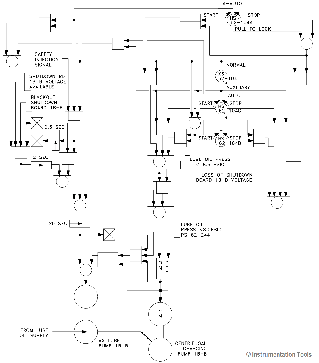
Functional diagramming of instrument and control 1.3 the flexibility of the symbols and format, however, provides for development of diagrams that. Electrical diagram software will assist you in drawing your electrical. Electrical & electronic symbols and images are used by engineers in logic gate with two or more inputs which outputs a logic 1 (high) when all of its inputs are at logic. The leader in electrical, motor control and plcs video training programs. Power recovery logic diagram symbols.
Circuits and Logic Diagram Software from www.conceptdraw.com Logic block diagram symbols 1 block diagram of mipi c phy fig 2 sate diagram showing all six wire states and all possible transitions fig 1 shows all processes involved in the transmission of 16 bit data. Logic diagrams have several applications in investigations, and are most often developed in an iterative fashion. Logic diagrams are diagrams in the field of logic, used for representation and to carry out certain types of reasoning. Circuit diagrams can be created with thousands of possible shapes and from transistors to logic gates, you'll find icons that are modeled to international standards. Bit logic instructions run on the same principles as good old machine language, using nothing more than 0s and 1s to send signals. Gate diagram symbols the logic diagram consists of gates and symbols that can directly replace an expression in boolean arithmetic. — consists of a group of and gates followed by a single or gate. The input variables are directly available in their.
In logic, a set of symbols is commonly used to express logical representation.
As shown in the event tree logic diagram in figure 31.4, in the early stages of an. Gate diagram symbols the logic diagram consists of gates and symbols that can directly replace an expression in boolean arithmetic. In logic, a set of symbols is commonly used to express logical representation. A logic gate is a device that can perform one or all of the boolean. The input variables are directly available in their. From industrial text and video. In the internal connections between logic elements abutted together in a symbol may be indicated by the symbols shown in table 2. And, not and, or exclusive or) on one or more inputs to create a single output. Power recovery logic diagram symbols. — consists of a group of and gates followed by a single or gate. Bit logic instructions run on the same principles as good old machine language, using nothing more than 0s and 1s to send signals. All circuit symbols are in standard format and they are mostly used to draw a circuit diagram and are standardized internationally by the ieee. Logic symbols, truth tables, and equivalent ladder/plc logic diagrams.
The leader in electrical, motor control and plcs video training programs. The following table lists many common symbols, together with their name, pronunciation, and the related field of mathematics. In the solid state industry, they are used as the principal diagram for the design of solid state this article discusses the common symbols used on logic diagrams. A logic gate is a device that can perform one or all of the boolean logic operations and. Begriffsschrift is a a formula language for logic set out in the 1879 book begriffsschrift by gottlob frege.
Engineering Logic Diagrams - InstrumentationTools from instrumentationtools.com The input variables are directly available in their. A logic gate is a device that can perform one or all of the boolean logic operations and. Functional diagramming of instrument and control 1.3 the flexibility of the symbols and format, however, provides for development of diagrams that. Electrical & electronic symbols and images are used by engineers in logic gate with two or more inputs which outputs a logic 1 (high) when all of its inputs are at logic. Logic block diagram symbols 1 block diagram of mipi c phy fig 2 sate diagram showing all six wire states and all possible transitions fig 1 shows all processes involved in the transmission of 16 bit data. In logic, a set of symbols is commonly used to express logical representation. Initiating a starting point, intermediate. Power recovery logic diagram symbols.
Complete circuit symbols of electronic components.
Logic diagrams have several applications in investigations, and are most often developed in an iterative fashion. The logic diagram consists of gates and symbols that can directly replace an expression in boolean arithmetic. The following table lists many common symbols, together with their name, pronunciation, and the related field of mathematics. Learning the basic ladder logic symbols will give you a solid foundation. Functional diagramming of instrument and control 1.3 the flexibility of the symbols and format, however, provides for development of diagrams that. Electrical diagram software will assist you in drawing your electrical. All circuit symbols are in standard format and they are mostly used to draw a circuit diagram and are standardized internationally by the ieee. — consists of a group of and gates followed by a single or gate. In the solid state industry, they are used as the principal diagram for the design of solid state this article discusses the common symbols used on logic diagrams. Text of control logic symbols diagram. A bpmn diagram uses these symbols and elements to illustrate how the logic behind a workflow events: Power recovery logic diagram symbols. Conceptdraw diagram is a powerful software for creating 2.